Bomb Jack Dissected
TL;DR: what I learned about the Bomb Jack arcade machine while writing an emulator for it.
![]()
I wrote a little Bomb Jack arcade emulator last week, mainly to learn how those early 8-bit arcade machines differed in design from 8-bit home computers.
Playing arcade games like Bomb Jack as a kid at the summer fair in my home town was one of those ‘life-changing moments’ that I only recognized much later as such. On a typical summer day, after I had spent all my coin budget on arcade games (usually didn’t take very long) I walked home with the head full of colors and sound effects, trying to figure out how those games worked. And then for the rest of the year spend all my after-school time trying to build rather poor impressions of those arcade games on my home computer, not unlike a cargo-cult worshipper on a post-WWII pacific island trying to build a US military radio station from wooden sticks.
At first I’ve been playing with the idea of writing a Pengo emulator, since this burned itself even more into my teenager-brain than Bomb Jack (this is my cargo-cult version of Pengo btw). But the Pengo arcade hardware would require new chip emulators for sound and video, while Bomb Jack only needs parts I already had working (Z80 as CPU and the AY-3-8910 for sound), so I went for Bomb Jack first.
Bomb Jack was also a good opportunity to finally add NMI (non-maskable interrupt) support to my Z80 emulator. None of the Z80 machines I emulated before used NMIs, and it didn’t make much sense to implement a feature when I have no way to test whether it even works.
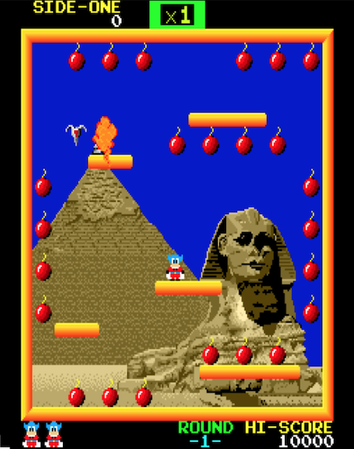
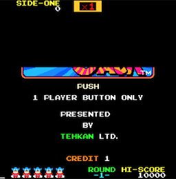
If you don’t know what Bomb Jack is, it looks like this (not sure if I got the screen aspect ratio right):
…you can check out the WebAssembly version of the emulator here:
https://floooh.github.io/tiny8bit/bombjack.html
After the boot sequence has finished and the hiscore screen appears, press 1 to insert coins, and than Enter (or any other key except arrows and space) to start a game.
In the game, use arrows keys for direction, and space to jump. While in the air tap space to reduce falling speed.
The source code is here:
https://github.com/floooh/chips-test/blob/master/examples/sokol/bombjack.c
This uses the chips headers to provide the Z80 and AY-3-8910 emulations, and the sokol headers as cross-platform wrapper (application entry, rendering, input and audio).
Step 1: Research
“Research” is a grand word for typing “Bombjack arcade hardware specs” into Google ;)
Compared to popular 80’s home computers (or even obscure Eastern European computers, which often still have active communities), there’s very little information for Bomb Jack on the web.
The two useful pieces of information I found are the original hardware schematics, and of course the MAME emulator source code.
There’s also a project which implements Bomb Jack in an FGPA where the VHDL source yielded some details where the schematics miss information.
The MAME sources may be a bit hard to grok, because the arcade emulations are usually just a bunch of macros describing how the different hardware parts interact, but there’s little actual source code to read.
But the macro-hardware-descriptions, and especially the comments are still very helpful to understand how the hardware works, and in those places where it all becomes a bit too obscure (for instance the video decoding part) a bit of trial and error, and running the finger through the hardware schematics is enough to clear up the confusion.
Hardware Overview
The most interesting feature of the Bomb Jack hardware is that it’s actually two computers duck-taped together, there’s a mainboard with a Z80 CPU and the video decoding hardware, and a separate soundboard with its own Z80 CPU and 3 (yes, three!!) AY-3-8910 sound chips.
The video decoding hardware on the mainboard isn’t implemented in an integrated circuit, instead it’s lots and lots of little general-purpose chips (taking up 6 of the 10 schematics pages). For the emulator I took a shortcut here: instead of emulating the video decoding hardware piece by piece, I only emulated its behaviour by creating the right visual output from the inputs, without caring too much how the hardware inbetween actually works.
This shortcut-approach is totally fine for a dedicated arcade machine which only ever needs to run one program. If the game looks and feels right, the emulation is “good enough”.
This ‘shortcut approach’ is also an important difference to most home computer emulators: some games demand a more precise emulation than others, for instance machines like the C64 or Amstrad CPC need a very precise emulation down to the clock cycle for the video systems for some games and graphics demos to work.
It also means that my existing CPU and sound-chip emulators are a bit overkill for Bomb Jack, for instance the Z80 CPU is running with machine-cycle granularity when a simpler and faster instruction granularity emulation would definitely be good enough.
The Main Board
Usually the first thing I try to find out when writing a new emulator is the memory map (where are the ROM and RAM areas, the video memory, and special IO addresses or ports).
The Bomb Jack mainboard only has one ‘interesting’ chip, the Z80 CPU running at 4 MHz. The entire remaining space on the mainboard is dedicated to the video decoding hardware (besides a couple of RAM and ROM chips).
The 16-bit address space looks like this:
- 0000..7FFF: 32 KByte ROM
- 8000..8FFF: 4 KByte general purpose RAM
- 9000..93FF: 1 KByte video RAM
- 9400..97FF: 1 KByte color RAM
- 9820..987F: 96 bytes sprite RAM
- 9C00..9CFF: 256 bytes color palette RAM
- 9E00, B000..B005, B800: IO ports
- C000..DFFF: 8 KByte ROM
The IO port area looks like this, some of the ports are write-only, some are read-only, and some have different functions when read or written:
- 9E00: write: the current background-image number, read: —
- B000: read: player 1 joystick state, write: NMI enable/disable mask
- B001: read: player 2 joystick state, write: —
- B002: read: coins and start buttons, write: —
- B003: read: CPU watchdog, write: ???
- B004: read: dip-switches 1, write: flip screen
- B005: read: dip-switches 2, write: —
- B800: write: command to soundboard, read: —
There’s a few noteworthy things:
- There’s a LOT of ROM (40 KBytes), and not a lot of RAM (about 7 KBytes, with only 4 KByte ‘general purpose RAM’)
- There’s only 2 KBytes for ‘display RAM’, divided into 2 chunks of 1 KByte, this looks very small for driving a colorful 256x256 display which appears to have per-pixel colors
- It’s a memory-mapped-IO system!
Memory-mapped-IO is a bit unusual for a Z80 machine, since one of the defining features of the Z80 is the separate 16-bit address space for device-IO, so that no precious memory address space needs to be wasted. Memory mapped IO is typically a feature found on computers with a 6502 CPU.
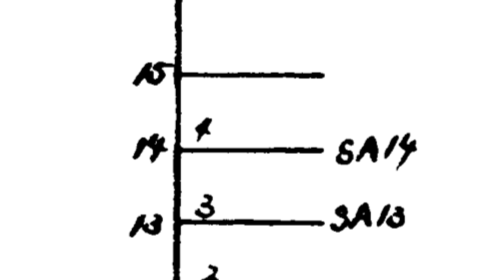
A quick look into the schematics confirms this: There’s no IORQ pin anywhere to be found on the mainboard CPU, only the MREQ pin is connected (which is used to initiate a memory read or write):
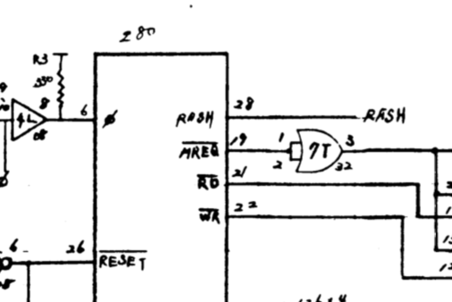
This means I don’t need to care about IO requests in the emulator’s mainboard CPU tick function at all, only about memory requests.
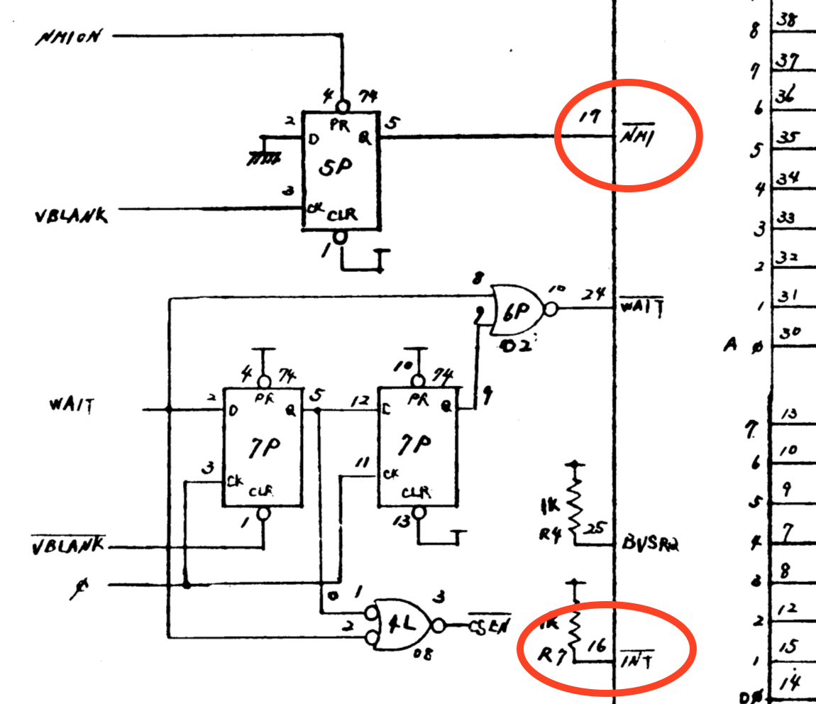
While snooping around the schematics, there’s another interesting mainboard CPU detail:
Only the NMI pin is connected, while the INT pin is always kept high/inactive (meaning no ‘regular’ maskable interrupts will happen, only non-maskable interrupts):
This is also quite unusual for a Z80 machine. All Z80-based home computers I’ve seen so far had it the other way around, they only used maskable interrupts, and never non-maskable interrupts. The maskable interrupt handling on the Z80 is very flexible and a big improvement over the rather primitive interrupt system of its ‘illegitimate father’, the Intel 8080, or its rival, the MOS 6502. But this improved flexibility is also more complex to implement in hardware (unless other Z80-family chips are used as interrupt source, those have the complex interrupt ‘daisy-chain’ protocol already baked in).
Ok, enough with the hardware details for now, onward to the emulator!
The Boot Sequence
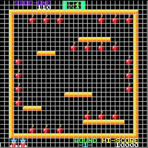
The next step after figuring out the memory configuration is to hook up an emulated CPU to the emulated memory map, write some adhoc visualization of the video memory content, and start ticking the CPU.
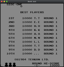
And surprisingly, this crude approach is often enough to run through the boot sequence and get something on screen. For the Bomb Jack emulator I simply took the content of the 1 KByte video memory at the range 0x9000 to 0x93FF as a 32x32 byte matrix, and when the byte is 0, render a black 8x8 pixel block, otherwise a white pixel block.
Then simply start the emulated CPU and hope for the best. And behold! Something recognizable appears:
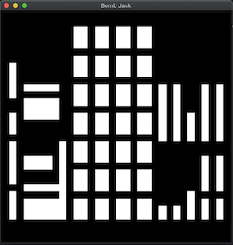
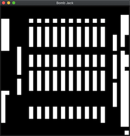
The left image looks a lot like the hardware testing screen during boot, and the right image like the hiscore screen that appears when the boot sequence is over:
…but 90 degrees rotated (which figures because arcade cabinets often had the screen in vertical ‘portrait mode’ orientation).
Ok very promising start!
The next step would be figuring out how to turn those white blocks into colored pixels… (huuuge jump now, the details are described below in the section on video decoding).
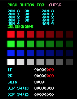
At first everything went quite smoothly, the test screen during boot had pixels and colors (later I noticed that the color decoding was all wrong, but anyway):
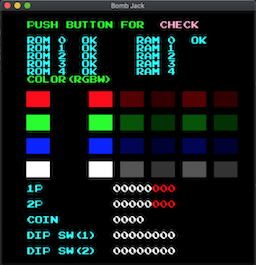
But where the hiscore screen should appear I ended up with a black screen. Hacking the background color to ‘not black’ revealed that the pixels are rendered, but the color palette was set to all black. Hmm…
After staring at this screen for a few minutes, I remembered that some colors on the hiscore screen were animated, and when there’s animation there needs to be some timer, and the obvious time source in this hardware config would be the display’s VSYNC signal, and the VSYNC is hooked up to the CPU’s NMI pin (or rather the VBLANK, which is the short duration between the VSYNC signal and the cathode ray tube beam travelling back to the top-left corner).
And I didn’t have implemented any of this yet…
On the next evening, after I had added a first version of the NMI handling to the Z80 emulation and hooked this up to an adhoc vsync/vblank counter in the mainboard’s CPU tick function, a lot of things suddenly started to happen!
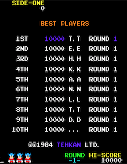
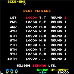
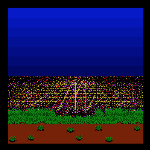
First, the hiscore screen had colors, and some of them were animated:
And after a few seconds, more exciting things happened! The hiscore screen disappeared, and a weird rendition of the first map showed up. This was clearly the arcade cabinet’s attract mode, I could see the first level, and some color-animated bombs which disappeared as an imaginary Bomb Jack jumped around the map collecting those bombs:
Colors were still totally wrong, but nevertheless: PROGRESS!
This was the right time to take care of the rest of the video decoding:
The Video Hardware
At first glance the Bomb Jack video hardware looks very powerful for an 8-bit machine from 1984: even though it only has a 256x256 pixel resolution, it can display 128 (out of 4096) colors at the same time, and render up to 24 hardware sprites (16x16 or 32x32 pixels big), all with per-pixel colors.
8-bit home computers of the time had about the same display resolution, but with many restrictions when it comes to colors, those restrictions can be seen nicely when comparing the Bomb Jack versions for the ZX Spectrum and Amstrad CPC with the Arcade version:
The ZX Spectrum version has a pretty good pixel resolution 256x192), but very few colors, and it suffers from the Spectrum’s typical ‘color clash’ effect (although the developers did a pretty good job to not make this too obvious):
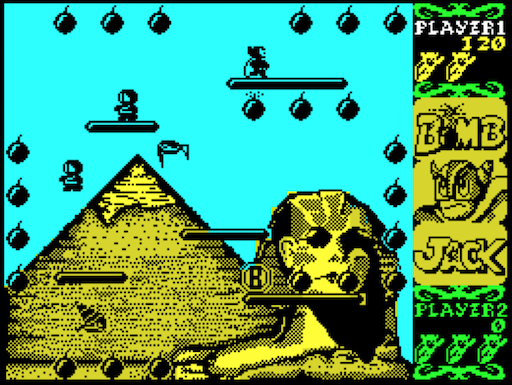
The Amstrad CPC version is more colorful, but in order to get more colors they had to switch to a low-resolution display mode (160x200), with the result that Jack and the monster are a lowres pixel mess:
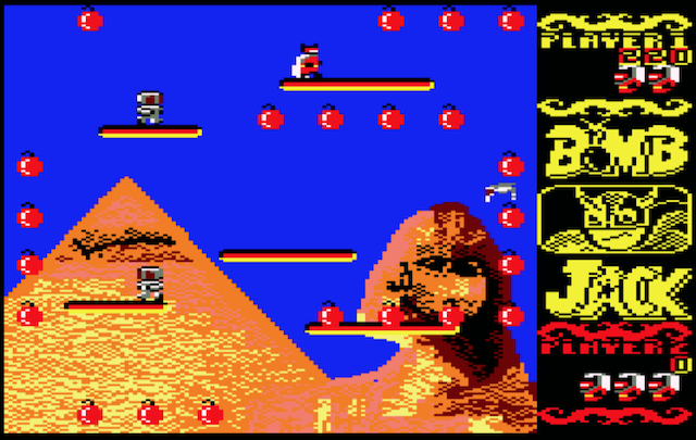
Compare that with the Arcade version which has about the same pixel resolution as the ZX Spectrum, but with many more colors and a per-pixel color resolution:
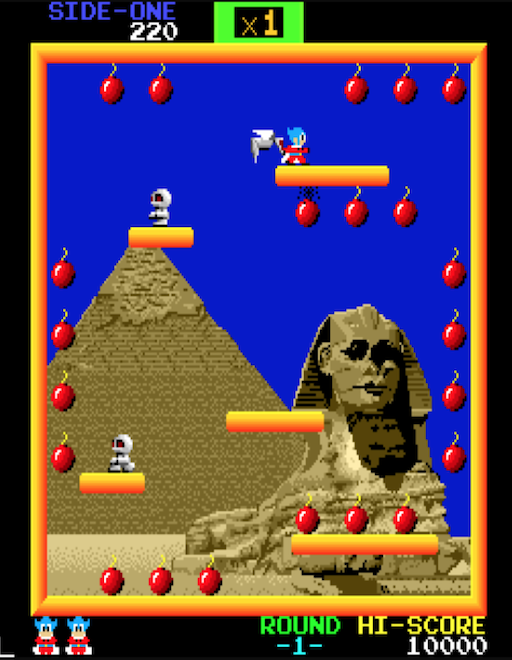
Now the interesting part is that the arcade version doesn’t have better graphics because it runs on more powerful hardware (it has more ROM to store more image data, but the ‘computing power’ is roughly the same), instead the hardware designers could focus on building a specialized machine for one specific type of game, they didn’t have to create a flexible and general purpose home computer.
Here’s how the display hardware works (at least my high-level interpretation of it):
The 3 Display Layers
The final Bomb Jack video output is composed from 3 layers: background layer, foreground layer and sprite layer.
This layer system has 2 main advantages:
- it implements a fairly clever hardware image compression to generate a colorful “high-resolution” image from very little data
- it drastically reduces the amount of CPU work necessary to update dynamic elements on the screen (even at 4 MHz, an 8-bit CPU by far doesn’t have enough performance to move that much stuff around on a 256x256 display at 60 Hz)
The video hardware is fairly different from what I’ve seen on 8-bit home computers, but since MAME has implemented generic helper classes for this sort of hardware I assume it was fairly common on arcade machines.
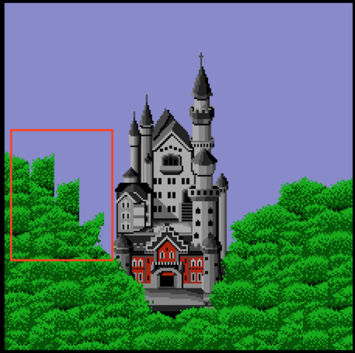
The Background Layer
The background layer can render 1 of 5 predefined background images hardwired into ROM. A background image is selected by writing a value between 1 and 5 to the address 0x9E00 (value 0 seems to be special and renders an all-black background).
The hardware actually seems to be capable of rendering 7 different images, but the game only uses 5. I was secretly hoping to find previously undiscovered image data in the ROMs. But alas, there aren’t any (and I probably wasn’t the first one to look either)
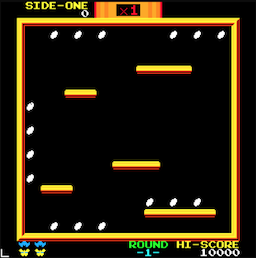
This is what the background layer for the first map looks like without the other two layers:
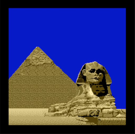
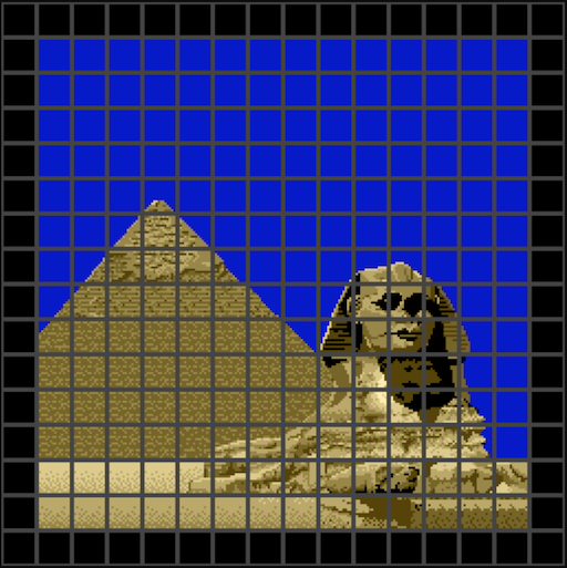
The background layer is built from 16x16 pixel tiles.
The advantage of building the background images from tiles is that identical tiles can be reused, so that less image data needs to be stored in ROMs. Note how the blue sky, parts of the pyramid and the sand below the pyramid use identical tiles:
The background layer hardware implements another trick to save some memory, tiles can be flipped horizontally. I almost didn’t implement this because I assumed that the software doesn’t use this hardware feature, until I noticed a subtile bug in the 3rd map background:
The same trick is used on the 5th map, it’s a bit harder to notice there though if you don’t know what to look for:
The Foreground Layer:
On top of the background layer is a ‘foreground layer’, which renders any non-movable parts of the screen that must still be updated by the CPU (mainly text, platforms and bombs). The layout is read from RAM (the 1 KB video RAM and 1 KB color RAM chunks).
This is what the isolated foreground layer looks like for the first map:
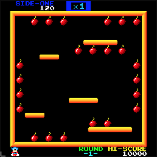
The foreground layer is also tiled (just like the background layer), but uses smaller 8x8 tiles:
The main advantage of keeping background and foreground in separate layers is that the CPU doesn’t need to care about storing and restoring background pixels when foreground elements are created or removed.
The Sprite Layer
Finally on top of the foreground layer, the hardware sprites are rendered. Everything that’s moving around on screen is done with sprites. The Bomb Jack hardware can render up to 24 sprites, where each sprite can be either 16x16 or 32x32 pixels, and sprites can be positioned with pixel resolution:
![]()
The 8x8 Tile Decoder
At the heart of the video decoding hardware is a color palette with 128 entries and an 8x8-pixel tile decoder. The job of the tile decoder is to generate a 7-bit color palette index for each of the 64 pixels in a tile.
Those 8x8 tiles are the building blocks for everything on screen, the 16x16 background tiles, 8x8 foreground tiles, and the 16x16 or 32x32 hardware sprites.
Here’s a functional diagram of this 8x8 tile decoder for the foreground layer rendering (as far as I understood it):
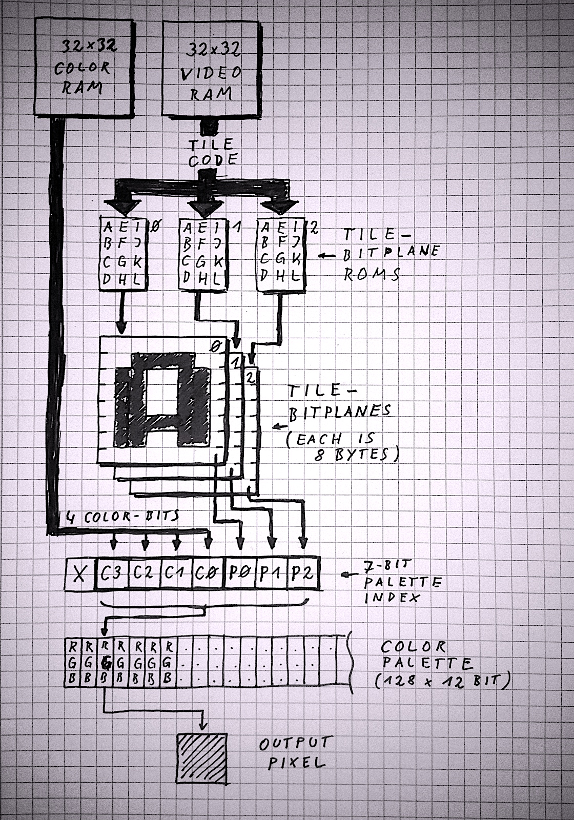
A top-to-bottom explanation of the diagram:
- The decoding process starts at the top by reading a ‘tile code’ byte from the video RAM (organized as a 32x32 matrix of tile codes), and a separate byte from the color RAM (also a 32x32 matrix). Fetching the tile- and color-codes from video RAM only happens for the foreground layer, but I added this because it makes the ‘overall picture’ a bit clearer. The 8x8 tile decoder itself only needs a tile- and color-code as input.
- The tile code is used as index to lookup 3 separate pixel bitplanes, those pixel bitplanes are always stored in ROM (you can think of the pixel bitplanes as font data or sprite sheets). Each of the 3 display layers has its own tile ROMs, and those ROMs are only visible to the decoding hardware, not to the CPU (so they don’t take up valuable CPU address space).
- A single pixel bitplane consists of 8 bytes per tile, with each byte holding 8 pixels (one bit per pixel). Since the pixel data for each tile is built from 3 bitplanes this means an 8x8 tile requires 24 bytes of ROM data to describe its appearance (3 bits per pixel).
- For each of the 64 pixels in a tile, a 7-bit value is constructed. The lower 3 bits are provided by the tile bitplanes read from the tile ROMs, and the higher 4 bits are provided by the color value byte. This basically means that each tile can select one of 16 ‘slots’ from the color palette, with each slot having 8 colors. Each tile pixel can select one of the 8 colors in the tile’s palette slot.
- This 7-bit index built from bitplanes and tile-color-value is used to lookup a 12-bit RGB color value from the color palette (4 bits per color channel). The color palette is located in RAM and can be manipulated by the CPU (as far as I have seen the video-, color- and palette-RAMs are write-only, at least the CPU never does read-accesses on those areas).
This is the basic tile decoding that’s used by each of the 3 display layers, but each layer decoding differs in small details:
- The foreground layer can actually render 512 different 8x8 tiles. This requires 9-bit tile codes, but the video RAM only provides 8 bits per tile. The 9th bit is ‘borrowed’ from the 5th bit of the color value (since only 4 bits of the color value are used to build the color palette index, there are 4 bits free for other purposes). If the 3 bits from the 8x8 tile bitplanes are all zero, the foreground pixel is transparent, and the background pixel ‘peeks through’.
- The background layer uses 16x16 tiles, so it only needs 16x16=256 tile code values and 256 color values to describe one background image in the background image ROM (512 bytes per image). The twist is though that the 16x16 pixel bitplanes are layed out as four 8x8 tiles, so that the same 8x8 tile decoder hardware can be used. As mentioned above, background tiles can be horizontally flipped, this is controlled with one of the ‘spare’ color value bits: if bit 7 of the color value is set, the tile will be flipped.
- Each hardware sprite can either be 16x16 pixels or 32x32 pixels, and the tile bitplanes are also layed out as 4 or 16 consecutive 8x8 tiles in the sprite tile ROMs. This means a 16x16 sprite needs 96 bytes, and a 32x32 sprite a whopping 384 bytes in the tile ROMs. As with foreground tiles, if all 3 pixel bitplane bits are zero, the sprite pixel is transparent.
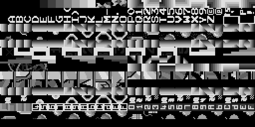
To get a better idea what the tile bitplanes look like, I wrote a little C program to convert the tile ROMs into PNG files (with the 3 bits per pixel converted into 8 levels of grey).
This is the foreground layer tile ROM. You can see the numbers and text font data, the platform tiles, bombs (split in half), parts of the Bomb Jack splash screen logo, and the score multiplier numbers that appear at the top of the screen (btw, everything is 90 degree rotated because the whole screen is rotated too):
Next the background tile ROM, this doesn’t look very recognizeable because what you see is the 8x8 tile decoding of 16x16 tiles. Each 16x16 tile is created from four neighbouring 8x8 tiles. But it’s possible to recognize the fairly regular pieces for the greek temple on map 2, the castle on map 3 and the sky scrapers on map 4.
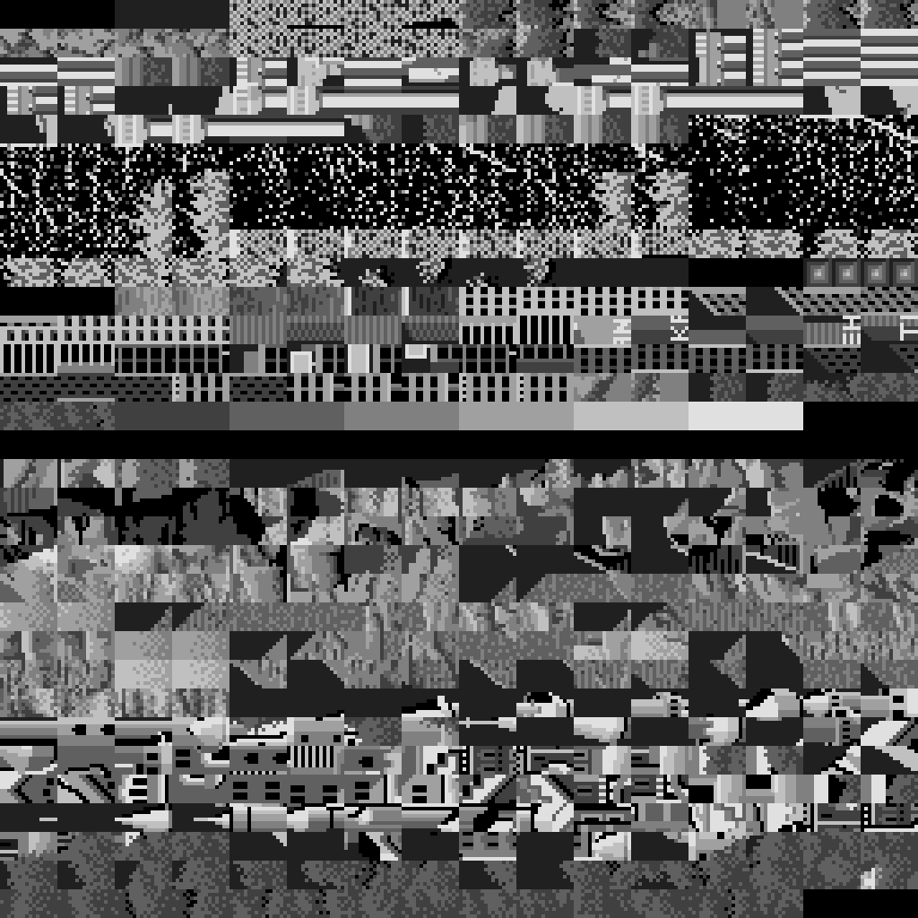
And finally the sprite tile ROM. The 16x16 sprites take up the upper half, and the 32x32 sprites the lower half.
![]()
An interesting hack in the Bomb Jack splash screen is that the logo is constructed from foreground tiles and sprites, I guess the developers were running out of foreground tile ROM, but had some space to spare in the sprite ROM:


The Sprite Hardware
The Bomb Jack sprite hardware is very powerful compared to what home computers provided at the time:
- up to 24 hardware sprites can be rendered, seemingly without restrictions how many sprites can be shown on a scanline
- sprites can be 16x16 or 32x32 pixels
- each sprite can choose one of 16 ‘8-color-slots’ in the shared color palette
- sprites have a per-pixel color resolution
- each sprite can be vertically and horizontally flipped
- each sprite can select one of 128 hardwired sprite images in ROM
The pixel- and color-decoding of the sprite system uses the same basic 8x8 tile decoding that’s also used in the background- and foreground-layer.
The sprite attributes are mapped into the address range 0x9820 to 0x987F, 96 bytes, 4 bytes per sprite. As far as I’ve seen, this is a write-only area, at least there are no CPU read accesses happening on this memory range.
Each sprite is described by 4 bytes:
- Byte 0:
- Bit 7: if set, this is a 32x32 sprite, otherwise 16x16
- Bits 6..0: 7 bits to define the tile code for the sprite, used to look up the sprite’s image bitplanes in the tile ROMs
- Byte 1:
- Bit 7: if set, the sprite is horizontally flipped
- Bit 6: if set, the sprite is vertically flipped
- Bits 3..0: 4 bits to provide the color value for the tile decoder
- Byte 2: the sprite’s X position on screen
- Byte 3: the sprite’s Y position on screen
It’s unclear what the bits 4 and 5 of byte 1 do, a comment in MAME has this to say:
 e        ? (set when big sprites are selected)
 f        ? (set only when the bonus (B) materializes?)
The Memory Mapped IO Ports
A few notes about the IO ports of the mainboard, as mentioned above, the IO ports look like this:
- 9E00: write: the current background-image number, read: —
- B000: read: player 1 joystick state, write: NMI enable/disable mask
- B001: read: player 2 joystick state, write: —
- B002: read: coins and start buttons, write: —
- B003: read: CPU watchdog, write: ???
- B004: read: dip-switches 1, write: flip screen
- B005: read: dip-switches 2, write: —
- B800: write: command to soundboard, read: —
The location 0x9E00 (background image selection) has already been handled above, and the location 0xB800 (sound command) will be handled in the next section, this leaves the locations 0xB000 to 0xB005:
Reading from location 0xB000 and 0xB001 returns the current state of the 2 joysticks. A set bit indicates that a joystick trigger is closed:
- bit 0: right direction
- bit 1: left direction
- bit 2: up direction
- bit 3: down direction
- bit 4: jump button pressed
The remaining 3 bits are ignored.
Reading from 0xB002 returns the state of the coin-detector and start buttons:
- bit 0: player 1 coin inserted
- bit 1: player 2 coin inserted
- bit 2: player 1 start button
- bit 3: player 2 start button
Reading from addresses 0xB004 and 0xB005 provides the state of dip-switches which are used to customize the arcade machine’s behaviour:
- B004:
- bits 0,1: how many ‘plays’ are given per coin (1, 2, 3 or 5)
- bits 2,3: the same for player 2
- bits 4,5: how many lifes per play (3, 4, 5 or 2)
- bit 6: whether the arcade machine is a ‘cocktail table’, or ‘upright’
- bit 7: whether to play sound while idle
- B005:
- bits 3,4: difficulty 1 (bird speed)
- bits 5,6: difficulty 2 (enemy number and speed)
- bit 7: ratio of special coin appearance
Finally, reading from address B003 implements a software watchdog. The CPU needs to read from this location frequently, otherwise the arcade machine will perform a hardware reset. If for some reason the game crashes, the hardware will automatically reboot.
Some IO port locations are writable:
- B000: whether to generate an NMI during vblank or not, this only seems to be disabled during the boot sequence
- B004: flip the entire screen, I haven’t seen this used, but I have a theory (see below)
The flip-screen functionality is a bit baffling, since when playing the game I haven’t seen this used. I have an idea what it does though, but need to do a bit more coding to confirm this. When the arcade machine is a ‘cocktail table’, the two players are sitting opposite each other. So my guess is that when the game switches from player 1 to player 2, it will ‘flip the screen’. I haven’t implemented 2-player mode in the emulator yet though.
The Sound Board
The soundboard is its own fully working computer with a Z80 CPU (running at 3 MHz), 3 sound chips (AY-38910, running at 1.5 MHz) and some RAM and ROM. The memory map of the soundboard looks quite simple:
- 0000..2000: 8 KBytes ROM
- 4000..4400: 1 KByte RAM
- 6000: sound command from the mainboard
Since there’s nothing of interest in the memory map above 0x8000, the CPU’s topmost address pin isn’t even connected:
The special location 0x6000 is a memory mapped IO port (8-bit latch) not backed by actual RAM. This is the same port that’s mapped to address 0xB800 on the mainboard, and this is the communication link between the mainboard and the soundboard.
The 3 sound chips are controlled through actual Z80 output instructions, not through memory-mapped ports. The AY-3-8910 only exposes two IO ports, the first one is used to store a register number, and the the second port is used to write or read the content of the register identified by the first port.
The IO map looks like this:
- 0x00: 1st sound-chip: select register
- 0x01: 1st sound-chip: access selected register
- 0x10: 2nd sound-chip: select register
- 0x11: 2nd sound-chip: access selected register
- 0x80: 3rd sound-chip: select register
- 0x81: 3rd sound-chip: access selected register
A few notes about the sound chip AY-3-8910:
This is a fairly standard part which also has been very popular in home computer designs of the time (for instance the Amstrad CPC, ZX Spectrum 128, MSX computers and more). The AY-3-8910 spawned many variations and clones, (for instance the Yamaha YM2149, which itself was the base for a whole family of more powerful sound chips).
The AY-3-8910 has 3 square-wave voices, a single noise generator which could be mixed into the 3 voices, and a single envelope generator. Since there was only one envelope generator for all three voices it wasn’t actually that useful, and most games used the CPU to modulate pitch and volume.
This means the AY-3-8910 needs more CPU intervention to produce good sound (unlike the much more autonomous SID chip in the C64 for instance).
It’s really surprising what one can do with 3 rather simple sound chips and a dedicated CPU to drive them though. Bomb Jack’s music and sound effects are much ‘richer’ than what I’ve heard from most home computer games.
The only really interesting thing about the soundboard is how it receives its command from the mainboard though.
The Sound Command Latch
The ‘sound latch’ is a single byte storage (an 8-bit latch) shared between the mainboard and soundboard. The latch is mapped to address 0xB800 on the main board, and to address 0x6000 on the soundboard.
The soundboard runs a very simple interrupt service routine when an NMI is triggered by the VSYNC which reads the hardware latch, and writes it to a normal memory location, along with setting a ‘signal bit’ which tells the ‘main loop’ that a new sound command has been received:
        ex af,af'               ;0066
        exx                     ;0067
        ld hl,04390h            ;0068
        set 0,(hl)              ;006b
        ld a,(06000h)           ;006d
        ld (04391h),a           ;0070
        exx                     ;0073
        ex af,af'               ;0074
        retn                    ;0075
The way the NMI pin is activated differs slightly from the mainboard:
On the mainboard, the NMI pin goes active for the duration of the VBLANK.
On the soundboard however, the NMI is activated when a VSYNC triggers, and stays active not for the duration of the VBLANK, but instead until the interrupt service routine reads from the latch at 0x6000.
When the hardware detects a read from location 0x6000 it performs two hardwired operations:
- the content of the sound latch is cleared to 0
- the NMI pin goes inactive
This is basically a simple debouncing which prevents that the same sound command is executed twice.
The only remaining question now was: how often does the main board write a new command (because this dictates how I would implement the emulation of the 2 boards).
With some printf-debugging I found out that the main board writes at most one new sound command per 60Hz frame, this simplified the design of the emulators ‘main loop’ a lot.
The problem of running 2 separate emulated computers side by side that need to communicate with each other is that emulation of one computer is only efficient if it can run a lot of cycles uninterrupted.
For instance the worst case would be:
- run computer 1 for one instruction
- run computer 2 for one instruction
- repeat…
My Z80 emulator is not optimized for entering and exiting the emulation for each instruction, because in this case it needs to flush and load the CPU state to and from memory at the start and end of each instruction. If the CPU can crunch through many instructions uninterrupted, it can keep (most of) the CPU state in registers and only flush state to memory at the last instruction.
So the ideal situation is to run an emulated system for an entire host system frame without interruption (for a 4 MHz CPU and 60Hz frames this means about 67k ticks per frame, or somewhere between 3k and 16k Z80 instructions).
For Bomb Jack I had to make sure that the mainboard doesn’t write a new command before the sound board is able to read the last command. Before I found out that the mainboard only writes at most one command per frame, I was considering building a complicated command queue, which catches writes to the mainboard sound latch, and stores a tick count and the command byte in a queue.
Then when the sound board executes its frame, it would pull a new command from the command queue when it has reached the command’s tick count.
This would work and would be ‘correct’, but also add quite a bit of code complexity.
In the end I decided for a much simpler solution without any queueing. Since the mainboard only writes one command per frame, I interleave the execution of the two computers so that each computer runs 2 ‘time slices’ per frame:
- run mainboard for first half of frame
- run soundboard for first half of frame
- run mainboard for second half of frame
- run soundboard for second half of frame
This guarantees that the soundboard properly sees every single command written by the mainboard while still running each emulation for thousands of ticks.
The big assumption about this is of course that the host system runs roughly at a 60Hz framerate :)
One Last Thing…
One last interesting trivia about the WebAssembly version of the emulator:
The compressed download size of all files when running the WebAssembly emulator is about 113 KBytes:
- about 2.5 KBytes for the HTML, CSS and ‘manually written’ JS
- 26.8 KBytes for the emscripten runtime JS file
- 83.7 KBytes for the .wasm file
The WASM file contains the embedded arcade machine ROMs.
Those ROMs have an uncompressed size of 112 KBytes.
So the entire compressed emulator with embedded ROMs is about the same size as the uncompressed ROMs :)
The 112 KByte ROMs compress to about 57 KBytes, this means the actual compressed code size in the WASM blob without the ROM data is under 30 KBytes (84 - 57).
Not too bad for an entire 8-bit system emulator I think ;)